Power rails/bars:
Power Junction and Power Supplies
When first building this, I was concerned about the power supplies having trouble with them all sharing common +5v and +12v lines. I was somewhat concerned that they would freak out, explode, short or otherwise fail in new and interesting ways. Thus far, this has not happened. I don't know enough about how the regulation and such in computer power supplies work to know if this should work. I am just bringing all the +5v and +12v lines from the power supplies together on some junction panels I had around and powering the drives from that. I've made sure that all the power supplies are the same model, but I have no idea if that is important or not.Power Junction Boxes:
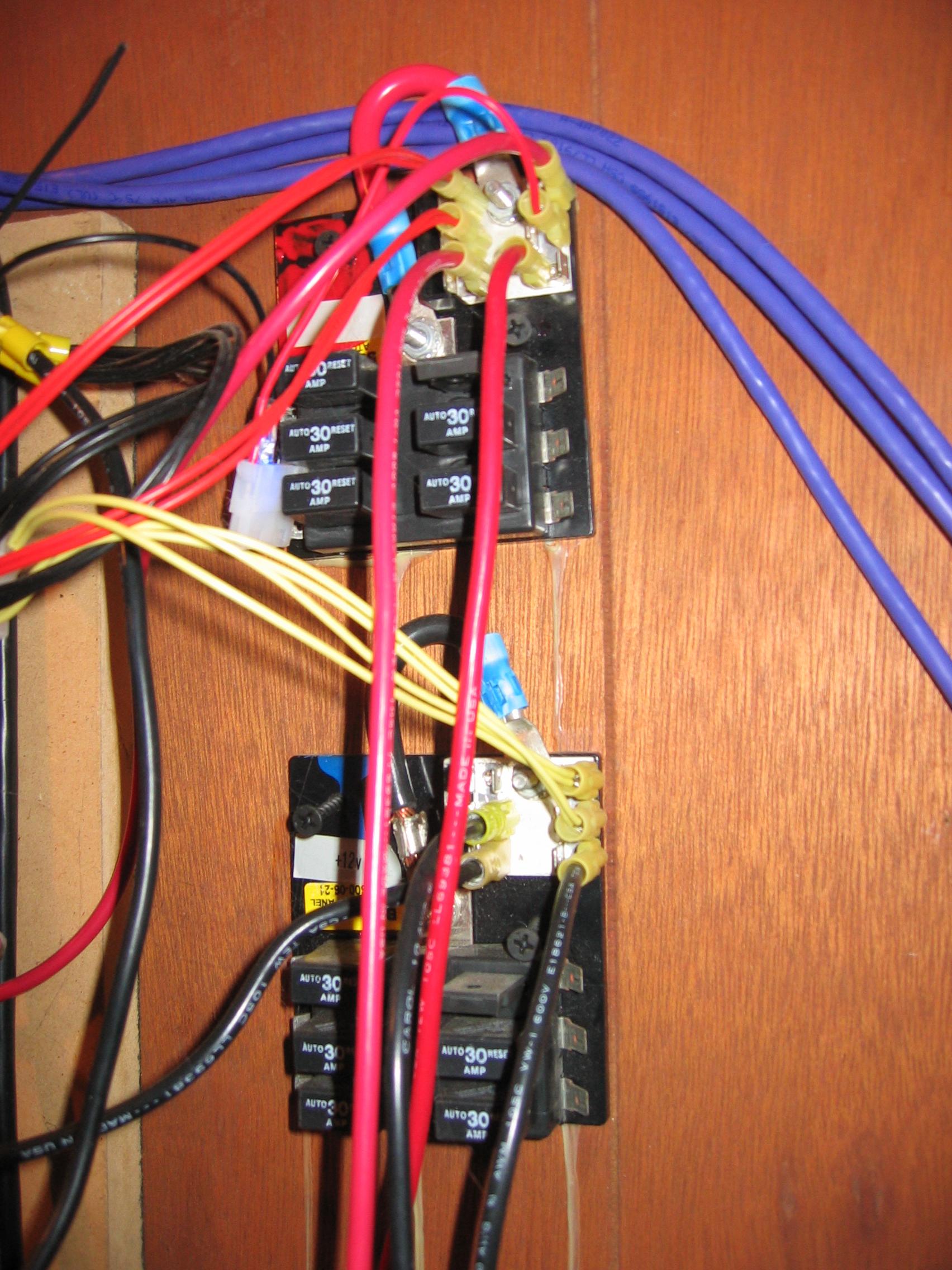
The junction boxes have 30 amp auto-resetting breakers built in, but I am not using those. With the higher amp loads I was noticing too much of a voltage drop across them. Also, by accident I found the power supplies have good automatic shutoff on short circuit features so the breakers are not needed.
Since all three power supplies must pull together to spin up the array, I needed to turn them all on at the same time. With good ol' AT power supplies, this would have been cake. But modern ATX power supplies use the motherboard to tell them to turn on. Some motherboards have features to power on automatically, but I didn't want to depend on that. After doing some reading of the ATX spec (which is actually quite readable) I found that for a motherboard to tell a power supply to turn on, it connects the green wire on the ATX header to ground. The power supply normally holds the green wire at a +5v signal voltage. So I simply cut the green wire on my ATX headers and connected it to my common ground. Now the power supplies kick on immediately when they get AC power and the motherboards seem to just accept it and POST normally. To give all the power supplied AC at the same time, I simply put them all on a single power strip with a switch. Easy as eating pancakes.
Standards
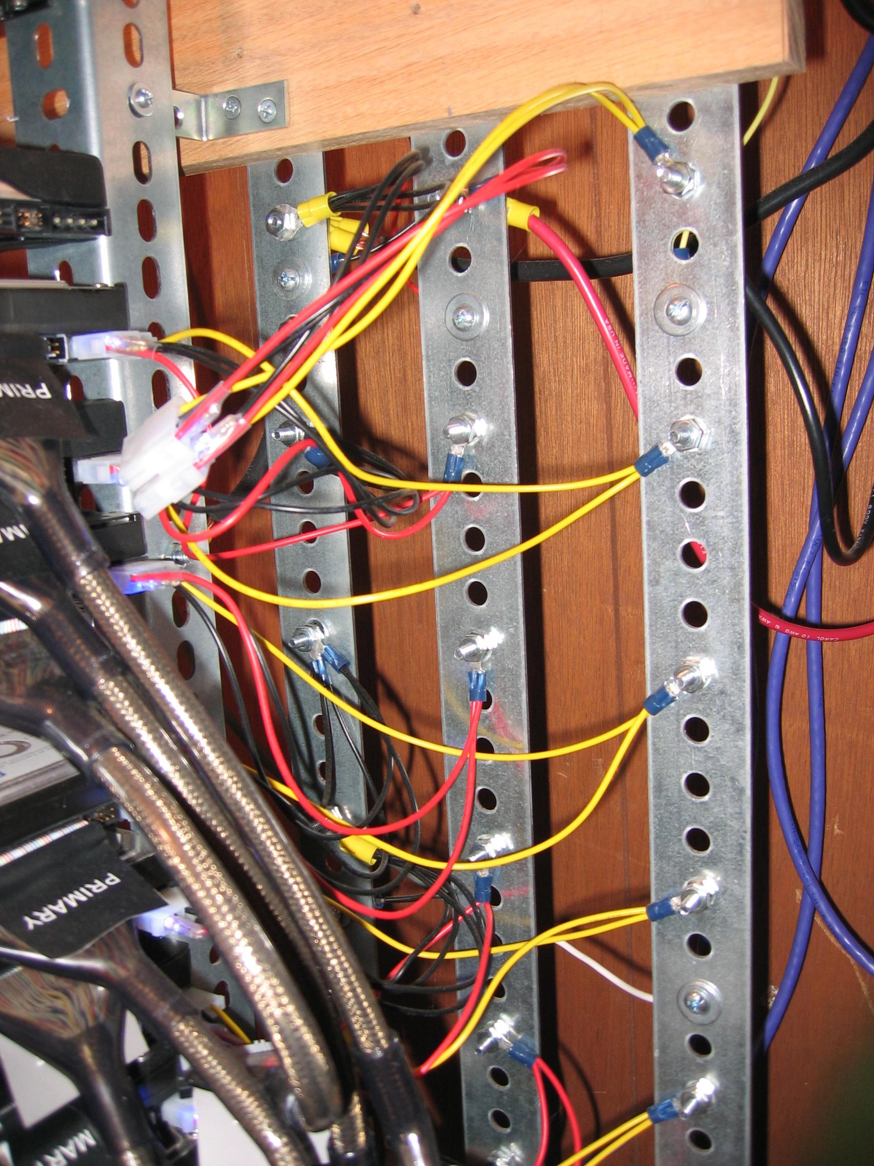
My color code is yellow for +12v (although I didn't have any heavy gauge yellow wire, so it is black from the collection panel to the power rail), red for +5v and black for ground. I didn't have a third power panel, so the ground is simply done with a bunch of (horrible) balls of connections made with bolts and crimp-ring connectors. The +5v and +12v are 10 gauge (awg) from the junction boxes to the rails. The ground is 6 gauge (awg) (overkill, but it is what I had on hand). For the peak of 50A or so I expect on 12v line, 10 awg is about right. It would be a little light if I expected that current load to be constant.Drive Connections
To connect the drives to the power bars, I bought a bunch of spare drive power connectors and cut them up. I attached crimp-ring connectors and bolted them to the appropriate power bars. Note: on a 4 pin molex connector, black (both of them) are ground, red is +5volts and yellow is +12volts. This required a bunch of washers, bolts and nuts. Washers especially, since the holes on the bars are quite large so without them the bolts would simply slip through. At the start of this project, I had no idea how much power drives actually used. There are the numbers on the drives, but I considered that non-sense or suspect. Now, after this project I can say that, a typical 3.5" drive spinning up uses about 1A on the 12v line (12 watts) and after spin up uses about 0.3A on the 12v and 0.3A on the 5v. So the spin up is a real bear. In it's current state with about 30 drives, the array uses 3 fairly standard (cheap) 500w power supplies. I have some voltmeters and ammeters on the lines so I can see it spike and settle down.A molex drive power connector:

main - Projects
prev - Projects -> Argus Array -> 1 Hardware -> 1 DriveArray
next - Projects -> Argus Array -> 1 Hardware -> 3 Motherboards

projects blog
©1999-2007 Joseph Gleason. Duplication of above materials prohibited without express written permision. All Rights Reserved.